How to modify a GRP hull to your needs-
Modifying a Dean's Marine HMS Kent hull in to HMS Niobe
by David Viewing
Prototype
I’ve long dreamt of building a late Victorian four-funnel cruiser and after building the little protected cruiser Pelorus, I wanted to compliment her with a larger ship. There are few if any working models of these very numerous large cruisers- I’ve not come across one personally-although there are many versions of the later three-funnel Kent. Partly I chose Niobe because there was not already an existing amateur or builder’s model, as far as I’ve found out but there is a model in Canada.
She was partly inspired by the rare opportunity of seeing the glorious builder’s model of ‘Good Hope’ in the IWM store at Duxford- they opened the crate especially for my visit. Good Hope was an armoured cruiser and I wanted something more contemporary with Pelorus, so this took me to the protected cruisers of the Diadem class. Initially I thought of building the lead ship Diadem, but the discovery that Admiralty plans were available in Canada for Niobe clinched it.
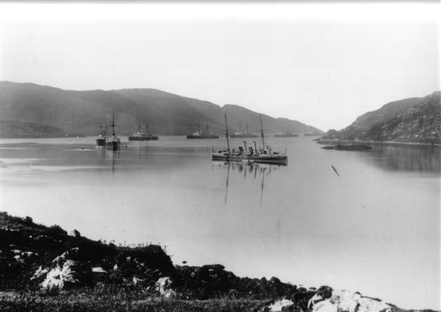
Niobe is mentioned in the wonderful Lawrence photograph of the Channel Fleet in Killary Harbour in County Mayo, Ireland on Sunday, 8th October, 1899 (see picture above)... I still don't know if she is actually in the picture- a large cruiser stands astern of Pelorus but appears to only have three funnels. Niobe features in the 1901 Royal Tour as well, in the Boer War where she accompanied the prototype large cruisers Powerful and Terrible, and in the 1917 Halifax Explosion where she was driven to the shore. And of course she was the first major ship in the new Canadian Navy in 1910.
I’ve long dreamt of building a late Victorian four-funnel cruiser and after building the little protected cruiser Pelorus, I wanted to compliment her with a larger ship. There are few if any working models of these very numerous large cruisers- I’ve not come across one personally-although there are many versions of the later three-funnel Kent. Partly I chose Niobe because there was not already an existing amateur or builder’s model, as far as I’ve found out but there is a model in Canada.
She was partly inspired by the rare opportunity of seeing the glorious builder’s model of ‘Good Hope’ in the IWM store at Duxford- they opened the crate especially for my visit. Good Hope was an armoured cruiser and I wanted something more contemporary with Pelorus, so this took me to the protected cruisers of the Diadem class. Initially I thought of building the lead ship Diadem, but the discovery that Admiralty plans were available in Canada for Niobe clinched it.
Niobe is mentioned in the wonderful Lawrence photograph of the Channel Fleet in Killary Harbour in County Mayo, Ireland on Sunday, 8th October, 1899 (see picture above)... I still don't know if she is actually in the picture- a large cruiser stands astern of Pelorus but appears to only have three funnels. Niobe features in the 1901 Royal Tour as well, in the Boer War where she accompanied the prototype large cruisers Powerful and Terrible, and in the 1917 Halifax Explosion where she was driven to the shore. And of course she was the first major ship in the new Canadian Navy in 1910.
HMS Niobe- 1897
|
HMS Pelorus- 1896
|
The Model
A long time ago before the idea of Niobe, I met a chap at an exhibition who had a Kent model and told me that he had acquired but not used a fibreglass hull moulding built to the MAP plans. The hull had been cut down to the main deck for some inexplicable reason, I bought the hull from him and it sat for many years in my model room with every prospect of being thrown out in the next clear out!
I had noticed that the overall dimensions of Kent and Niobe were quite similar although Niobe is high sided almost to the stern and Kent is cut away after the foc’sle. Once I had plans from Canada I was pleased to see that the hull form was indeed very similar (the stern was a completely different shape) and it would be possible to use the cut down Kent hull with new built-up sides. The Admiralty plans included a number of cross-sections and the lines matched extremely well.
This left the difficult issue of internal access because the on these ships the superstructure forms a narrow long island along the centre line and doesn’t reach the beam. Eventually I decided that narrow lift-out deck sections would just be wide enough to allow access for the motors and lead acid battery. Not an ideal solution because the funnel stays can’t be carried to the gunwales but in my opinion an acceptable compromise in a working model.
Niobe’s stern lines and rudder frame are entirely different to Kent but this didn't present a big problem in fabrication terms. Both frame and rudder were built-up in brass sections to get a very strong result, as the rudder in heavy working models like this are quite vulnerable.
Power
I have access to a source of 12 pole 24v hydraulic pump motors in a frame exactly lie old style car heater motors which I had used in my battleship Mars. I found that the motors would turn about 1500rpm with a 12v source. The advantage of using them is a very wide speed range from the propellers only just turning up to full power- all in complete silence- and of course no temperature rise. The complication was that I wanted the shafts to lie horizontally in the bottom of the hull, not sloped up like in a speed boat. Niobe was a reciprocating engined ship and the crankshafts were low on the floor of the engine rooms almost in the bilges. The large diameter of the chosen motors meant indirect drive and I decided to experiment with toothed belts. Initially I experimented with a 1:2 reduction drive but found that the 750rpm was not enough. I wanted Niobe to be faster than a battleship not slower!
A sensible decision would have been 1:1, but since I had the parts I decided to try 2:1 and so it has remained. Niobe is very fast indeed, quite an advantage on a mixed model boat lake. Motor current never exceeds 1A even with this high loading and the power transmitted is sufficient to make the belts skip if handled carelessly. With a 12Ah of battery capacity running time is adequate and has been demonstrated at six continuous non-stop hours on one occasion. The belts are tensioned by a balanced spring-loaded idler, the idler wheels are two ball bearing side-by-side.
Niobe has inward turning propellers and differential power managed by the transmitter. I’ve found receiver based v-tail mixers to be highly prone to drifting, a problem where in a model where any revolution of the prop causes it drift on the water. The inward turning props were important for ‘walking’ the model away from the quay and the model nicely demonstrates this.
The rudder can be slaved to the differential power at low speeds and a transmitter switch to allow it to be separated when at high speed. This is because at high speeds motor differential is only available by slowing one motor and the resulting loss of speed is very noticeable- in any case the scale rudder authority is adequate.
The shaft tunnels were made from brass tube with sealed ball races at the driving end to the massive side loads of the toothed belts. A special ply bulkhead fits around the ball race tubes and transmits the load directly to the hull. So far this has stood up well. The propeller end has long plain bearings and the stern brackets are made from brass bar laboriously filed to shape. The shafts themselves are 5mm stainless steel. The dimensions and alignment of the shafts follow closely the Admiralty drawings. Niobe’s propellers are standard ‘Victorian’ style from from the wonderful people at Swann Foundry, Banbury, who trade as ‘Propshop’ (re-traded as Protean Design by the propeller designer).
The Design
From the beginning I decided to use CAD in Niobe. The first step was to scan the Canadian Admiralty plans using an A3 scanner. For CAD I use TurboCad, this has been almost a lifelong affliction starting with version 2 back in 1995. TurboCad is the only semi capable CAD programme that was available within an amateur budget but I’m aware that in this modern age many professionals are turning to Google SketchUp. It’s an affliction because it been, and still is, riddled with bugs that have the tendency to trash entire projects at some late design stage, and in a way that you won’t notice until it’s too late! Niobe’s drawings are an example of this tendency having mysteriously lost the sequence of the embodied jpeg files over which the model is laid up (I believe that new entrants to the field start with 3D design packages and never suffer the agony of 2D scaling that I have experienced).
The A3 scans were stitched together with much juggling of scale and rotation to get an acceptable result (I’ve tried various ‘stitching’ software but none of them could handle the size and resolution that I needed). So what I’m referred to is numerous jpg scans hand manoeuvred into visual alignment and finally associated by merging into a single object. All this could be avoided by scanning the document one one go! Sometime later TurboCad ‘forgot’ which jpg files went in which scale outlines and I had to do the whole job again! I aligned to stitched drawings so that the bottom of the keel fitted a true horizontal line in the CAD programme and this fortunately gave vertical lines like masts and funnels that were bang on vertical- these Victorian ships were built square!
Scans of the decks were lined up with the side elevation and the whole thing was checked and checked again so that a line vertically from, say, the base of a ventilator would intersect exactly with the same feature in all the drawings. This revealed one of the great powers of CAD- the ability to project precise vertical and horizontal lines.
Over the scans I laid all the lines that I needed. The hull lines I took directly from the small number of frame stations illustrated in the admiralty plans. The fibreglass ‘floor pan’ fitted extremely well with these lines, although quite a bit of adjustment had to be made. Each project- a piece of hull side for instance- could be printed in exact scale directly, simply by setting the model scale to be 1/96. This means that dimensions taken in CAD are displayed at 1/96 scale and print outs can be used directly. There are plenty of ‘gotcha’s’ with this technology, one is when laying out the hull sides is to remember to correct for curvature. Two portholes that are a certain distance apart on the Admiralty drawings are not necessarily that distance apart on the side of the ship, especially near the bow and stern. Its necessary to project these details onto a suitable deck plan, and then flatten this to get a template suitable for model making.
Etching
One big advantage of using CAD is that you can directly from Admiralty plans to an etch tool. Niobe uses numerous etches to reproduce components that would be too time consuming, or practically impossible, to reproduce manually. A classic example would be the numerous gratings that appear throughout the ship.
Unfortunately etching companies do not like TurboCad files (they have experienced the pain mentioned earlier!) and so it’s normally necessary to export the etch drawings in an accepted format like AutoCad.
Building the Hull
The frames were cut from 1/2” ply using fill size templates printed directly from CAD. The sides were pulled in somewhat to reproduce the marked tumble-home shape in the real ships. Stringers, again in 1/2” ply, were added in to stiffen the hull. The biggest issue in this type of composite construction is finding glues that will stick to all the materials at once!
A breakthrough was in discovering that GRP moulding resin can be mixed with harder in a liquid form and will attach very strongly to plywood. This was used to secure the frames inside the GRP hull. The ply stringers were fixed to the frames with waterproof PVA and any gaps filled with P40 diluted with GRP resin. This job was done in the garage for ventilation purposes!
The bilge keels are often a weak point in models, since they naturally act as hand grips when lowering the ship into the water. In Niobe I decided that these ‘grab handles’ would be up to the job! They are made from thick polystyrene sheet 1/2” wide which tabs also about 1/2” wide that fits into slots cut into the hull with the ever useful cutting disc. Once installed they are sealed on the outside with runs of cyano super glue, just about the only thing that will stick to both polystyrene and GRP. Once this had set to form a meniscus, the whole hull was water tested and any leaked plugged with more cyano.
After testing the inside of the hull either side of the tabs were built up with P40, although P40 doesn’t stick too well to polystyrene but the action of moulding it over the tabs gave them adequate strength and protects the slotted hull so that rough handling won’t cause leaks.
I decided to use polystyrene sheet for the hull sides in order to get the right surface finish but this obviously gave uncertainties about the joint with the GRP hull that would run the length of the model. GRP resin will not stick to polystyrene so to overcome this I first planked the hull sides with 1/16” ply which would reliably bond to the plywood framing and edges of the GRP hull. When this was complete I laminated the outer skin in thin Plasticard using cyano to attach it.
The casemates moulded in to the GRP hull were cut out after the stringers had been added. They are replaced with sections of brass tubing rebated into the sides. The conical effect below the waterline is formed with filler and the barbette are back filled to avoid leaks. The casemate guns are arranged to lie parallel to the hull by drilling the holes with a long extended drill made from 12” of steel bar with the drill soldered on the end. This ensures that the guns are both horizontal and that they don’t project in a way they would allow the barrel to scrape alongside the jetty. The gun ports are disguised with etched brass covers- in the real ships these 6 inch guns would be run in and the ports closed altogether.
The ram bow was back filled with P40 for a considerable distance because a head on collision could otherwise crack the hull. The shape of the ram was adjusted to follow the scale outline. The stern was also back filled around the rudder post and then cut away to follow the scale form. The rudder frame was sawn from brass sheet and provision was made for a lower pintle bearing which has not yet been fitted. The rudder itself is made from a sawn brass frame with plates bolted on with 12BA screws and nuts. The design closely follows the original, not too difficult since the aftermath of the Halifax Explosion meant that many photos were taken after she was dry-docked.
Niobe’s decks are 1/16” ply and are permanently attached at the bow and stern. Midships, the boat deck is continuous ply for about 2 inch inboard, sprung from the plywood frames which are undercut to disguise their presence. Below, the main deck lies on the frames and is made in two pieces joined at the centreline in such a way that they could be unscrewed and taken out through the gap in the boat deck if required.
Two opening hatches were needed for access to motors and battery. This is an unfortunate compromise but the edges of these hatches are disguised as much as possible by overlapping planking. In addition, these hatches are relatively out of sight on the main deck. One carries the uptake building and the centre two funnels, and the other the engine room skylight and the spar deck. These hatches are not watertight and the model has taken water over the foc’sle in very poor weather conditions which has ended up in the bilges. If I built the model again, I would seal the main deck and use smaller motors in some form of removable frame that could be accessed though the skylight opening so that the hatches would conform to the size of the superstructure with coaming around them.
Niobe’s upper deck armament was mounted on raised platforms fore and aft and these are removable with a certain amount of sealing, giving access to the radio and steering gear. The arrangement of these platforms is clear in the photographs and plans, but different in Amphritrite, showing that the design of seemingly identical ships still vary in detail.
Plating
I’ve avoided the issue of showing hull plating on the basis that the builder’s models don’t show it either. This is a convenient cop-out for a difficult problem because no shell expansion exists for Niobe (that I so far aware of). This means that any plating would be guesswork anyway, and model plating so often exaggerates that effect to the detriment of the model in my opinion.